A bus can be constructed in two ways
1. Using Multiplexer
2. Using three state buffer
2. Using three state buffer
Three state buffer is a useful device that allows us to control, when current passes through a device and when it does not.
Bus system construction using tri-state buffer
- As in a conventional gate, 1 and 0 are two states.
- The third state is a high impedance state.
- The third state behaves like an open circuit.
- If the output is not connected, then there is no logical significance.
- It may perform any type of conventional logic operations such as AND, OR, NAND, etc

Active “LOW” Tri-state Buffer
| Symbol | Truth Table | ||

Tri-state Buffer
|
Enable/Control | IN | OUT |
| 0 | 0 | 0 | |
| 0 | 1 | 1 | |
| 1 | 0 | Hi-Z | |
| 1 | 1 | Hi-Z | |
| Read as Output = Input if Enable/Control is NOT equal to “1” | |||
Active “HIGH” Tri-state Buffer
| Symbol | Truth Table | ||

Tri-state Buffer
|
Enable/Control | IN | OUT |
| 0 | 0 | Hi-Z | |
| 0 | 1 | Hi-Z | |
| 1 | 0 | 0 | |
| 1 | 1 | 1 | |
| Read as Output = Input if Enable/Control is equal to “1” | |||
Three-state buffer gate
- To form a single bus line, all the outputs of the 4 buffers are connected together.
- The control input will now decide which of the 4 normal inputs will communicate with the bus line.
- The decoder is used to ensure that only one control input is active at a time.
- The diagram of a 3-state buffer can be seen below.
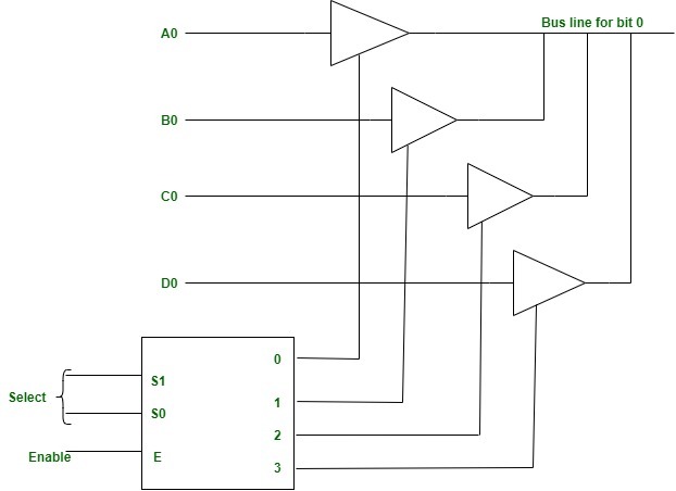
Figure – Bus Line with three-state -buffers
Some Other Question :
- Explain the Common Bus System with its diagram.
- Explain the register transfer language with example.
- What is high impedance state in three-state buffer? Explain three state gate in designing bus system.
- Explain 4-bit Arithmetic Circuit with its Function Table
- Discuss the phases of Instruction Cycle with flowchart.
- Explain the basic working principle of the Control Unit of basic computer using diagram.