A basic computer has 8 registers, memory unit and a control unit. The diagram of the common bus system is as shown below.
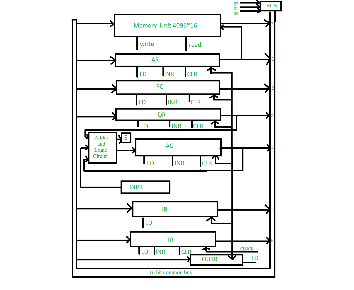
| Abbreviation | Register name |
|---|---|
| OUTR | Output register (Gives Output) |
| TR | Temporary register (Store data for temporary) |
| IR | Instruction register (Holds the instruction of execution) |
| INPR | Input register (Input Data/Values) |
| AC | Accumulator (Store the results of ALU) |
| DR | Data register (Hold data) |
| PC | Program counter ( Hold the address of next instruction ) |
| AR | Address register (Hold the address) |
Step By Step Process of Common Bus System :
Step 1: Program Counter
Step 2: Address Register
Step 3: Memory Unit
Step 4: Data Register
Step 5: Arithmetic and logical Operations Performed
Step 6: Accumulator
Step 7: Output Register Or Temporary Register
PC → AR → MU → DR → ALU → AC → OUTR
Connections:
The
outputs of all the registers except the OUTR (output register) are
connected to the common bus. The output selected depends upon the binary
value of variables S2, S1 and S0. The lines from common bus are
connected to the inputs of the registers and memory. A register receives
the information from the bus when its LD (load) input is activated
while in case of memory the Write input must be enabled to receive the
information. The contents of memory are placed onto the bus when its
Read input is activated.
Various Registers:
4 registers
DR, AC, IR and TR have 16 bits and 2 registers AR and PC have 12 bits.
The INPR and OUTR have 8 bits each. The INPR receives character from
input device and delivers it to the AC while the OUTR receives character
from AC and transfers it to the output device. 5 registers have 3
control inputs LD (load), INR (increment) and CLR (clear). These types
of registers are similar to a binary counter.
Some Other Question :
- Explain the Common Bus System with its diagram.
- Explain the register transfer language with example.
- What is high impedance state in three-state buffer? Explain three state gate in designing bus system.
- Explain 4-bit Arithmetic Circuit with its Function Table
- Discuss the phases of Instruction Cycle with flowchart.
- Explain the basic working principle of the Control Unit of basic computer using diagram.