
GUJARAT TECHNOLOGICAL UNIVERSITY
Computer Network (3150710) Summer 2022 Paper Solution
Q.1 (a) What
is the difference between a host and an end system? List several different
types of end systems. 03
There is no difference between host and end system. In network,
all the devices and systems are termed as host or end system. So, they can be
used alternatively throughout the network.
Types of end systems:
The different types of end systems are as follows
·
Personal Computer Systems
·
Workstations
·
Web Servers
·
E-mail Servers
·
Personal Digital Assistant (PDA)
·
Television
·
Mobiles
·
Internet connected devices and many others
(b) Explain
IP Address, Physical Address and Port Number in Brief. 04
1. IP address:
An Internet Protocol address (IP address) is the logical address of our network
hardware by which other devices identify it in a network. IP address stands for
Internet Protocol address which is a unique number or a numerical
representation that uniquely identifies a specific interface on the network.
Each device that is connected to internet an IP address is assigned to it for
its unique identification.
Addresses in IPv4 are 32-bits long example, 12.244.233.165
And Addresses in IPv6 are 128-bits
example, 2001:0db8:0000:0000:0000:ff00:0042:7879
2. Physical
Address: A physical address (also real address, or binary address), is a
memory address that is represented in the form of a binary number on the
address bus circuitry in order to enable the data bus to access a particular
storage cell of main memory, or a register of memory-mapped I/O device.
3. Port Number:
Port number is the part of the addressing information used to identify the
senders and receivers of messages in computer networking. Different port
numbers are used to determine what protocol incoming traffic should be directed
to. Port number identifies a specific process to which an Internet or other
network message is to be forwarded when it arrives at a server. Ports are
identified for each protocol and it is considered as a communication
endpoint.
(c) Draw the
layered architecture of OSI reference model and write at least two services
provided by each layer of the model. 07
OSI is the reference model designed to divide the entire
communication operation into multiple processes. This model divides basic communication
functions into seven different layers as shown in the figure below. Here two
end communication devices are named Application A and Application B. Each layer
communicates with their adjacent layer while adding or removing header and
trailer.

When the data is being transmitted it goes from bottom to top in
the OSI layer architecture. Each layer follows its own function:
1. Physical
layer:
·
This layer deals with the transfer of bits
over a communication channel, for example copper wire pairs, coaxial cable,
optical fibre.
·
This layer is concerned with the particular
choice of system parameters such as voltage level and signal duration, also
setup and release of physical connection as well as mechanical aspect such as
socket type and number of pins.
2. Data link
layer:
·
This layer converts bits into group of bits
called frames. It also adds additional information related to frame such as
address and correction bits and bits to define the boundaries of frames.
·
This control is practically important when
the transmission link is prone to transmission error. Check bits ensures the
detection of error if any happens during transmission also address bits help in
the flow control frames.
3. Network
Layer:
·
This layer combines multiple frames forming a
packet while sending the data and when it receives a data it separates frames
from the packet.
·
This layer provides routing of packet across
the communication network and when doing so it is required that the nodes
through which packets are passing are always connected to the network. This
makes the network layer most complex layer in the OSI model.
·
This layer also deals with the congestion
that occurs from time to time due to surge in the traffic in the network.
4. Transport
Layer:
·
The role of this layer is to provide
appropriate address information so that the messages can be delivered to the
appropriate destination session layer.
·
It also performs various functions such as
error free transfer of information by the error detection and recovery
techniques and sequence and flow control.
·
This layer also does the segmentation and
reassembly or blocking and unblocking to match the size of the message produced
by the session layer to the packet sizes that can be handled by the network
layer.
5. Session
Layer:
·
This layer enhances the reliability of
transfer of data over transport layer by providing means of dialogue between
two applications. Such as in some communication manners data transfer is half
duplex where both applications takes turn in transferring the data. This
facility is supported by session layer.
·
This application of session layer becomes
useful while transferring large files to provide synchronization points from
which error recovery can be initiated instead of transferring large files
again.
6.
Presentation Layer:
·
This layer provides presentation of data to
the application layer. Different computers use different coding technique to
represent different symbols. It is the function of this layer to convert the
data into presentable form in the receiving application.
·
In other words this layer converts machine
dependent information into machine independent and vice versa at the receiving
end.
7. Application
Layer:
·
This layer closet to the user. It provides
user services that are frequently required by the application in communication.
These services include e-mail, name services, login service, network management
etc.
Q.2 (a)
Explain the role of Domain Name Server (DNS) in Internet? 03
Domain Name System (DNS) is a
hierarchical naming system built on a distributed database for computers,
services, or any resource connected to the Internet or a private network. Most importantly,
it translates human readable domain names into the numerical identifiers
associated with networking equipment, enabling devices to be located and
connected worldwide. Analogous to a network “phone book,” DNS is how a browser
can translate a domain name (e.g., “facebook.com”) to the actual IP address of
the server, which stores the information requested by the browser.
The eight steps in a DNS lookup:
1. A user
enters a domain name (e.g., facebook.com) into their browser, and the browser
sends the query via their internet service provider isp to a DNS recursive
resolver.
2. The DNS recursive resolver, in
turn, sends a query to the root DNS nameserver (.).
3. The root server returns to the
resolver the address of the top-level domain (i.e., “TLD”) DNS root server,
which has the needed information for the facebook.com domain.
(Examples of a top- level domain tld include “.com”, “.net”, and
“.org,” which each TLD having it’s own root DNS server.)
4. In turn, the resolver then sends
the information request to the Top-Level Domain server (In this case, the
“.com” TLD nameserver).
5. The TLD name server responds to
the resolver with the targeted IP address of the domain’s nameserver. (In this
case, the DNS server for “facebook.com”.)
6. Next, the DNS recursive resolver
sends the query to the domain’s DNS server.
7. The domain’s DNS server then
returns the IP address to the DNS resolver for the requested domain (e.g.,
“facebook.com”).
8. Finally, the DNS resolver returns
the IP address of the requested domain to the requesting web browser. The
browser sends the HTTPS request to the targeted IP address, and the server with
that address returns the webpage, which renders in the user’s browser.

(b) Explain
functionality of Repeater, HUB, Bridge, Switch, Router and Gateway. 04
1. Repeater – A repeater operates at
the physical layer. Its job is to regenerate the signal over the same network
before the signal becomes too weak or corrupted to extend the length to which
the signal can be transmitted over the same network. An important point to be
noted about repeaters is that they do not amplify the signal. When the signal
becomes weak, they copy it bit by bit and regenerate it at its star topology
connectors connecting if original strength. It is a 2-port device.
2. Hub – A hub is a
basically multi-port repeater. A hub connects multiple wires coming from
different branches, for example, the connector in star topology which connects
different stations. Hubs cannot filter data, so data packets are
sent to all connected devices. In other words, the collision
domain of all hosts connected through Hub remains one. Also, they do
not have the intelligence to find out the best path for data packets which
leads to inefficiencies and wastage.
3. Bridge – A bridge operates at the
data link layer. A bridge is a repeater, with add on the functionality of
filtering content by reading the MAC addresses of the source and destination.
It is also used for interconnecting two LANs working on the same protocol. It
has a single input and single output port, thus making it a 2 port device.
4. Switch – A switch is a multiport
bridge with a buffer and a design that can boost its efficiency (a large number
of ports imply less traffic) and performance. A switch is a data link layer
device. The switch can perform error checking before forwarding data,
which makes it very efficient as it does not forward packets that have errors
and forward good packets selectively to the correct port only. In other
words, the switch divides the collision domain of hosts, but the broadcast
domain remains the same.
5. Routers – A router is a device like a switch that routes data
packets based on their IP addresses. The router is mainly a Network Layer
device. Routers normally connect LANs and WANs and have a dynamically updating
routing table based on which they make decisions on routing the data packets.
The router divides the broadcast domains of hosts connected through it.

6. Gateway – A gateway, as the name suggests, is a passage to connect two networks that may work upon different networking models. They work as messenger agents that take data from one system, interpret it, and transfer it to another system. Gateways are also called protocol converters and can operate at any network layer. Gateways are generally more complex than switches or routers. A gateway is also called a protocol converter
(c) Consider
the 7-bit generator, G=10011, and suppose that D has the value1010101010. What
is the value of R? 07

So, the 7-bit generator, G=10011, and D has the value 1010101010. Then the value of R is 0100.
Q.3 (a)
Discuss parity check for error detection in data transfer. 03
How to
Detect and Correct Errors?
To detect and correct the errors, additional bits are added to the
data bits at the time of transmission.
·
The additional bits are called parity
bits. They allow detection or correction of the errors.
·
The data bits along with the parity bits form
a code word.
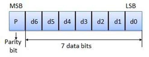
Parity
Checking of Error Detection
It is the simplest technique for detecting and correcting errors.
The MSB of an 8-bits word is used as the parity bit and the remaining 7 bits
are used as data or message bits. The parity of 8-bits transmitted word can be
either even parity or odd parity.
Even parity -- Even parity means the
number of 1's in the given word including the parity bit should be even
(2,4,6,....).
Odd parity -- Odd parity means the
number of 1's in the given word including the parity bit should be odd
(1,3,5,....).
Use of
Parity Bit
The parity bit can be set to 0 and 1 depending on the type of the
parity required.
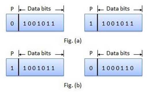
·
For even parity, this bit is set to 1 or 0
such that the no. of "1 bits" in the entire word is even. Shown in
fig. (a).
·
For odd parity, this bit is set to 1 or 0
such that the no. of "1 bits" in the entire word is odd. Shown in
fig. (b).
How Does
Error Detection Take Place?
Parity checking at the receiver can detect the presence of an
error if the parity of the receiver signal is different from the expected
parity. That means, if it is known that the parity of the transmitted signal is
always going to be "even" and if the received signal has an odd
parity, then the receiver can conclude that the received signal is not correct.
If an error is detected, then the receiver will ignore the received byte and
request for retransmission of the same byte to the transmitter.

(b) List and
briefly describe three types of switching fabrics used in Routers. Which, if
any, can send multiple packets across the fabric in parallel? 04
(c) Describe
Go Back N and Selective Repeat protocol. 07
Both Go-Back-N Protocol and Selective Repeat
Protocol are the types of sliding window protocols. The main difference
between these two protocols is that after finding the suspect or damage in sent
frames go-back-n protocol re-transmits all the frames whereas selective repeat
protocol re-transmits only that frame which is damaged.
|
GO-BACK-N SLIDING WINDOW PROTOCOL |
SELECTIVE REPEAT SLIDING WINDOW PROTOCOL |
|
It acts by retransmitting all the frames in the particular order after
a damaged or corrupted frame is encountered |
It acts by
retransmitting only those frames which are damaged or corrupted while
transmission |
|
It uses cumulative acknowledgements |
It uses
independent acknowledgement |
|
In this protocol, there is a great amount of wastage of the bandwidth,
if there is a high error rate in the transmission |
In this protocol,
there is less wastage as compared to Go-Back-N sliding window protocol in
retransmission of frames |
|
In this, there is absolutely no need for sorting the sender or the
receiver side |
In this
protocol, there is a need for the sorting of frames that too on the receiver
side to maintain the proper sequence of frames |
|
Sliding window size of receiver is 1. For sender, it is N |
Sliding
window size of receiver is N. For sender, it is same as receiver which is N |
|
It is fairly less complicated than other protocols |
It is
slightly more complicated solely because it uses strategies, logics, etc.
which is not present in all protocols |
|
The receiver does not store any frame that is received after
encountering the damaged frame, till the damaged frame is retransmitted |
The
receiver stores the frames that are received after encountering the damaged
frame in a buffer, till the damaged frame is resent by the sender |
|
It is more frequently used as compared to Selective repeat Sliding
Window |
It is less
frequently used as compared to Go-Back-N |
Q.3 (a) Give
difference between connection oriented and connection less services. 03
|
Comparison Parameter |
Connection-oriented Service |
Connection Less Service |
|
Related
System |
It is
designed and developed based on the telephone system. |
It is
service based on the postal system. |
|
Definition |
It is used
to create an end to end connection between the senders to the receiver before
transmitting the data over the same or different network. |
It is used
to transfer the data packets between senders to the receiver without creating
any connection. |
|
Virtual
path |
It creates
a virtual path between the sender and the receiver. |
It does
not create any virtual connection or path between the sender and the
receiver. |
|
Authentication |
It
requires authentication before transmitting the data packets to the receiver. |
It does
not require authentication before transferring data packets. |
|
Data
Packets Path |
All data
packets are received in the same order as those sent by the sender. |
Not all
data packets are received in the same order as those sent by the sender. |
|
Bandwidth
Requirement |
It
requires a higher bandwidth to transfer the data packets. |
It
requires low bandwidth to transfer the data packets. |
|
Data
Reliability |
It is a
more reliable connection service because it guarantees data packets transfer
from one end to the other end with a connection. |
It is not
a reliable connection service because it does not guarantee the transfer of
data packets from one end to another for establishing a connection. |
|
Congestion |
There is
no congestion as it provides an end-to-end connection between sender and
receiver during transmission of data. |
There may
be congestion due to not providing an end-to-end connection between the
source and receiver to transmit of data packets. |
|
Examples |
Transmission
Control Protocol (TCP) is an example of a connection-oriented service. |
User
Datagram Protocol (UDP), Internet Protocol (IP), and Internet Control Message
Protocol (ICMP) are examples of connectionless service. |
(b) Why do
HTTP, FTP, SMTP, and POP3 run on top of TCP rather than on UDP? Name one
application that uses UDP and why? 04
·
TCP is a connection oriented Protocol and is
suited for applications which use high reliability and where transmission time
is relatively less critical for applications than that use UDP.
·
Whereas UDP needs applications that need
fast, efficient transmission such as games.
·
Its feature of handling small queries from
huge number of clients is useful for servers. Hence this is the reason why TCP
is the most commonly used application protocol for HTTP, FTP, SMTP, IMAP, and
POP3.
·
Also Because TCP is more reliable, and HTTP,
FTP, SMTP, and POP3cannot be affordable using UDP while UDP cannot transmit
packet and guarantee a well order delivery.
·
TCP is a connected-oriented network so packet
will be delivered to the destination.
There are
three types of applications that are best suited for UDP:
·
Applications that can tolerate some data
loss, but require little or no delay
·
Applications with simple request and reply
transactions
·
Unidirectional communications where reliability
is not required or can be handled by the application
Many video and multimedia applications, such as VoIP and Internet
Protocol Television (IPTV) use UDP. These applications can tolerate some data
loss with little or no noticeable effect. The reliability mechanisms of TCP
introduce some delay that can be noticeable in the quality of the sound or
video being received.
Other types of applications well suited for UDP are those that use
simple request and reply transactions. This is where a host sends a request and
may or may not receive a reply. These types of applications include:
·
DHCP
·
DNS - May also use TCP
·
SNMP
·
TFTP
(c) Explain
RDT 2.0. 07
Reliable Data Transfer (RDT) 2.0 protocol works on a Reliable
Data Transfer over a bit error channel. It is a more realistic model for
checking bit errors that are present in a channel while transferring it may be
the bits in the packet are corrupted. Such bit errors occurs in the physical
components of a network when a packet is transmitted,
propagated, or buffered. In this, we will be assuming that all
transmitted packets that are received in the order in which they were sent
(whether they are corrupted).
In this condition we ask the user to send ACK (acknowledgement,
i.e., the packet that received is correct and it is not corrupted) or NAK
(negative acknowledgement i.e. the packet received is corrupted). In this
protocol we detect the error by using Checksum Field, checksum is a
value that represents the number of bits in a transmission message. To check
the checksum value calculated by the end user is even slightly different from
the original checksum value, this means that the packet is corrupted, the
mechanism that is needed to allow the receiver to detect bit errors in a packet
using checksum is called Error Detection.
This techniques allow the receiver to detect, and possibly correct
packet bit errors. In this we only need to know that this technique require
that extra bits (beyond the bits of original data to be transferred) be sent
from the sender to receiver; these bits will be gathered into the packet
checksum field of the RDT 2.0 data packet.
Another technique is Receiver Feedback since the
sender and receiver are executing on different end systems, the only way for
the sender to learn of the receiver’s scenario i.e., whether or not a packet
was received correctly, it is that the receiver should provide explicit
feedback to the sender. The positive (ACK) and negative acknowledgement (NAK)
replies in the message dictation scenario are an example of such feedback. A
zero value indicate a NAK and a value of 1 indicate an ACK.

Q.4 (a) Give
difference between flow controls verses Congestion Control. 03
|
S.NO |
Flow Control |
Congestion Control |
|
1. |
Traffic
from sender to receiver is controlled, to avoid overwhelming the slow receiver. |
Traffic
entering the network from a sender is controlled by reducing rate of
packets. Here, the
sender has to control/modulate his own rate to achieve optimal network
utilization. |
|
2. |
Flow
control is typically used in data link layer. |
Congestion
control is applied in network and transport layer. |
|
3. |
In this,
Receiver’s data is prevented from being overwhelmed. |
In this,
Network is prevented from congestion. |
|
4. |
In flow
control, sender needs to take measures to avoid receiver from being overwhelmed
depending on feedback from receiver and also in absence of any feedback. |
In this,
many algorithms designed for transport layer/network layer define how
endpoints should behave to avoid congestion. |
|
5. |
Types of
Flow control are 1.
Stop and Wait – For every frame
transmitted, sender expects ACK from receiver. 2.
Sliding Window – ACK needed only after
sender transmits data until window is full, which is allocated initially by
receiver. |
Mechanisms
designed to prevent network congestions are 1.
Network Queue Management 2.
Explicit Congestion Notification 3.
TCP Congestion control |
(b) What is
HTTP? Differentiate its persistent and no persistent types with
request-response behavior of HTTP. 04
Hypertext Transfer Protocol (HTTP) is an application-layer protocol for transmitting hypermedia documents, such
as HTML. It was designed for communication between web browsers and web
servers, but it can also be used for other purposes.
Non-persistent and persistent are
the two types of HTTP connections used to connect the client with the
webserver. The non-persistent connection has connection type 1.0, while
the persistent connection has connection type 1.1.
Non-persistent
The non-persistent connection takes a total time of 2RTT + file
transmission time. It takes the first RTT (round-trip time) to establish
the connection between the server and the client. The second RTT is taken to
request and return the object. This case stands for a single object
transmission.
After the client receives the object in non-persistent, the
connection is immediately closed. This is the basic difference between persistent
and non-persistent. The persistent connection ensures the transfer of multiple
objects over a single connection.
Persistent
A persistent connection takes 1 RTT for the connection and then
transfers as many objects, as wanted, over this single connection.
RTT stands for the round-trip
time taken for an object request and then its retrieval. In other words, it is
the time taken to request the object from the client to the server and then
retrieve it from the server back to the client.
(c) Explain
distance vector routing algorithm. 07
The Distance vector algorithm is iterative,
asynchronous and distributed.
- Distributed: It
is distributed in that each node receives information from one or more of
its directly attached neighbors, performs calculation and then
distributes the result back to its neighbors.
- Iterative: It
is iterative in that its process continues until no more information is
available to be exchanged between neighbors.
- Asynchronous: It
does not require that all of its nodes operate in the lock step with each
other.
- The
Distance vector algorithm is a dynamic algorithm.
- It is
mainly used in ARPANET, and RIP.
- Each
router maintains a distance table known as Vector.
How the DVR
Protocol Works
·
In DVR, each router maintains a routing
table. It contains only one entry for each router. It contains two parts − a
preferred outgoing line to use for that destination and an estimate of time
(delay). Tables are updated by exchanging the information with the neighbor’s
nodes.
·
Each router knows the delay in reaching its
neighbors (Ex − send echo request).
·
Routers periodically exchange routing tables
with each of their neighbors.
·
It compares the delay in its local table with
the delay in the neighbor’s table and the cost of reaching that neighbor.
·
If the path via the neighbor has a lower
cost, then the router updates its local table to forward packets to the
neighbor.
Example −
Distance Vector Router Protocol
In the network shown below, there are three routers, A, B, and C,
with the following weights − AB =2, BC =3 and CA =5.
Step 1 − In this DVR
network, each router shares its routing table with every neighbor. For example,
A will share its routing table with neighbors B and C and neighbors B and C
will share their routing table with A.

|
Form A |
A |
B |
C |
|
A |
0 |
2 |
3 |
|
B |
|||
|
C |
|
Form B |
A |
B |
C |
|
A |
|||
|
B |
2 |
0 |
1 |
|
C |
|
Form C |
A |
B |
C |
|
A |
|||
|
B |
|||
|
C |
3 |
1 |
0 |
Step 2 − If the path via a
neighbor has a lower cost, then the router updates its local table to forward
packets to the neighbor. In this table, the router updates the lower cost for A
and C by updating the new weight from 4 to 3 in router A and from 4 to 3 in
router C.
|
Form A |
A |
B |
C |
|
A |
0 |
2 |
3 |
|
B |
|||
|
C |
|
Form B |
A |
B |
C |
|
A |
|||
|
B |
2 |
0 |
1 |
|
C |
|
Form C |
A |
B |
C |
|
A |
|||
|
B |
|||
|
C |
3 |
1 |
0 |
Step 3 − The final updated routing
table with lower cost distance vector routing protocol for all routers A, B,
and C is given below −
Router A
|
Form A |
A |
B |
C |
|
A |
0 |
2 |
3 |
|
B |
2 |
0 |
1 |
|
C |
3 |
1 |
0 |
Router B
|
Form B |
A |
B |
C |
|
A |
0 |
2 |
3 |
|
B |
2 |
0 |
1 |
|
C |
3 |
1 |
0 |
Router C
|
Form C |
A |
B |
C |
|
A |
0 |
2 |
3 |
|
B |
2 |
0 |
1 |
|
C |
3 |
1 |
0 |
OR Q.4 (a) Explain CSMA/CD Protocol. 03
Carrier Sense Multiple Access with Collision Detection (CSMA/CD)
is a network protocol for carrier transmission that operates in the Medium
Access Control (MAC) layer. It senses or listens whether the shared channel for
transmission is busy or not, and defers transmissions until the channel is
free. The collision detection technology detects collisions by sensing
transmissions from other stations. On detection of a collision, the station
stops transmitting, sends a jam signal, and then waits for a random time
interval before retransmission.
The
algorithm of CSMA/CD is:
·
When a frame is ready, the transmitting
station checks whether the channel is idle or busy.
·
If the channel is busy, the station waits
until the channel becomes idle.
·
If the channel is idle, the station starts
transmitting and continually monitors the channel to detect collision.
·
If a collision is detected, the station
starts the collision resolution algorithm.
·
The station resets the retransmission
counters and completes frame transmission.
The
algorithm of Collision Resolution is:
·
The station continues transmission of the
current frame for a specified time along with a jam signal, to ensure that all
the other stations detect collision.
·
The station increments the retransmission
counter.
·
If the maximum number of retransmission
attempts is reached, then the station aborts transmission.
·
Otherwise, the station waits for a back off
period which is generally a function of the number of collisions and restart
main algorithm.

(b) Why are
different inter-AS and intra-AS protocols used in the Internet? 04
BGP or Border Gateway Protocol is used for inter-AS or Autonomous
System protocols. RIP or Router Information Protocol and OSPF or Open Shortest
Path First protocol are used for intra-AS protocols.
Inter-AS protocol helps in the controlled distribution of routing
information. Intra-AS protocol comprises of the policy issues which play a less
important role in choosing routes.
Inter-AS routing is policy-oriented so the performance of the
routes used is given secondary importance. Intra-AS focuses on performance.
(c) Explain
Link-State routing algorithm. 07
The Link State Routing Algorithm is an interior protocol
used by every router to share information or knowledge about the rest of the
routers on the network. The link state routing algorithm is distributed by
which every router computes its routing table.
With the knowledge of the network topology, a router can make its
routing table. Now, for developing the routing table, a router uses a shortest
path computation algorithm like Dijkstra's algorithm along with the
knowledge of the topology. The routing table created by each router is
exchanged with the rest of the routers present in the network, which helps in
faster and more reliable delivery of data.
A router does not send its entire routing table with the rest of
the routers in the inter-network. It only sends the information of its
neighbors. A router broadcasts this information and contains information about
all of its directly connected routers and the connection cost.
Now, the process of transferring the information about a router's
neighbors is termed flooding. A router transfers the information to all
the inter-network routers except its neighbors. Every router that receives the
information sends the information copies to all its neighbors. In this way, all
the routers of the inter-connected network have the same copy of the
information.
This information exchange only occurs when there is a change in
the information. Hence, the link state routing algorithm is effective. Refer to
the image below for the basic overview of the router and updating done by the
link state routing algorithm.

Q.5 (a)
Explain in brief socket, multiplexing and demultiplexing. 03
Socket
A socket is one endpoint of a two way communication
link between two programs running on the network. The socket mechanism provides
a means of inter-process communication (IPC) by establishing named contact
points between which the communication take place.
Like ‘Pipe’ is used to create pipes and sockets is created
using ‘socket’ system call. The socket provides
bidirectional FIFO Communication facility over the network. A
socket connecting to the network is created at each end of the communication.
Each socket has a specific address. This address is composed of an IP address
and a port number.
Socket are generally employed in client server applications. The
server creates a socket, attaches it to a network port addresses then waits for
the client to contact it. The client creates a socket and then attempts to
connect to the server socket. When the connection is established, transfer of
data takes place.
Multiplexing
Multiplexing is the process of collecting the data from multiple
application processes of the sender, enveloping that data with headers and
sending them as a whole to the intended receiver.
·
In Multiplexing at the Transport Layer, the
data is collected from various application processes. These segments contain
the source port number, destination port number, header files, and data.
·
These segments are passed to the Network Layer
which adds the source and destination IP address to get the datagram.
Demultiplexing
Delivering the received segments at the receiver side to the
correct app layer processes is called demultiplexing.
·
The destination host receives the IP
datagrams; each datagram has a source IP address and a destination IP address.
·
Each datagram carries 1 transport layer
segment.
·
Each segment has the source and destination
port number.
·
The destination host uses the IP addresses
and port numbers to direct the segment to the appropriate socket.
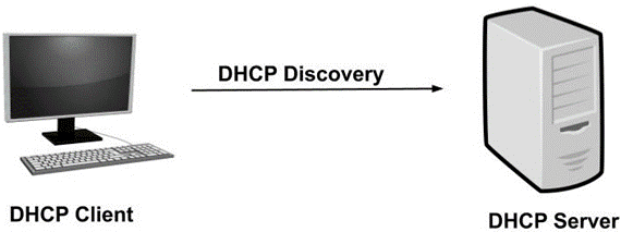
(b) How DHCP protocol works? 04
Dynamic Host Configuration Protocol is a network
management protocol that is used to dynamically assign the IP address and other
information to each host on the network so that they can communicate
efficiently. DHCP automates and centrally manages the assignment of IP address
easing the work of network administrator. In addition to the IP
address, the DHCP also assigns the subnet masks, default
gateway and domain name server (DNS) address and
other configuration to the host and by doing so, it makes the task of network administrator
easier.
How do DHCP works?
DHCP works at the application layer to dynamically assign the IP
address to the client and this happens through the exchange of a series of
messages called DHCP transactions or DHCP conversation.
- DHCP
Discovery: The DHCP client broadcast messages to
discover the DHCP servers. The client computer sends a packet with the
default broadcast destination of 255.255.255.255 or the
specific subnet broadcast address if any configured. 255.255.255.255 is
a special broadcast address, which means “this network”:
it lets you send a broadcast packet to the network you’re connected to.
- DHCP
Offer: When the DHCP server receives the DHCP
Discover message then it suggests or offers an IP address (form IP address
pool) to the client by sending a DHCP offer message to the client. This
DHCP offer message contains the proposed IP address for DHCP client, IP
address of the server, MAC address of the client, subnet mask, default
gateway, DNS address, and lease information.

1. the proposed
IP address for DHCP client (here 192.168.1.11)
2. Subnet mask
to identify the network (here 255.255.255.0)
3. IP of the
default gateway for the subnet (here 192.168.1.1)
4. IP of DNS
server for name translations (here 8.8.8.8)
- DHCP
Request: In most cases, the client can
receive multiple DHCP offer because in a network there are
many DHCP servers (as they provide fault tolerance). If the IP addressing
of one server fails then other servers can provide backup. But, the client
will accept only one DHCP offer. In response to the offer, the client
sends a DHCP Request requesting the offered address from
one of the DHCP servers. All the other offered IP addresses from remaining
DHCP servers are withdrawn and returned to the pool of IP available
addresses.

- DHCP
Acknowledgment: The server then sends Acknowledgment to
the client confirming the DHCP lease to the client. The server might send
any other configuration that the client may have asked. At this step, the
IP configuration is completed and the client can use the new IP settings.

(c) Explain
TCP segment structure and justify the importance of its field values. 07
TCP Segment structure –
A TCP segment consists of data bytes to be sent and a header that is added to
the data by TCP as shown:

The header of a TCP segment can range from 20-60 bytes. 40 bytes
are for options. If there are no options, a header is 20 bytes else it can be
of upmost 60 bytes.
Header fields:
- Source
Port Address –
A 16-bit field that holds the port address of the application that is sending the data segment. - Destination
Port Address –
A 16-bit field that holds the port address of the application in the host that is receiving the data segment. - Sequence
Number –
A 32-bit field that holds the sequence number, i.e, the byte number of the first
byte that is sent in that
particular segment. It is used to reassemble the message at the receiving end
of the segments that are received out of order.
- Acknowledgement
Number –
A 32-bit field that holds the acknowledgement number, i.e, the byte number that the receiver expects to receive next. It is an acknowledgement for the previous bytes being received successfully. - Header
Length (HLEN) –
This is a 4-bit field that indicates the length of the TCP header by a number of 4-byte words in the header, i.e if the header is 20 bytes(min length of TCP header), then this field will hold 5 (because 5 x 4 = 20) and the maximum length: 60 bytes, then it’ll hold the value 15(because 15 x 4 = 60). Hence, the value of this field is always between 5 and 15. - Control
flags –
These are 6 1-bit control bits that control connection establishment, connection termination, connection abortion, flow control, mode of transfer etc. Their function is:
·
URG: Urgent pointer is valid
·
ACK: Acknowledgement number is valid( used in
case of cumulative acknowledgement)
·
PSH: Request for push
·
RST: Reset the connection
·
SYN: Synchronize sequence numbers
·
FIN: Terminate the connection
- Window size
–
This field tells the window size of the sending TCP in bytes. - Checksum
–
This field holds the checksum for error control. It is mandatory in TCP as opposed to UDP. - Urgent
pointer –
This field (valid only if the URG control flag is set) is used to point to data that is urgently required that needs to reach the receiving process at the earliest. The value of this field is added to the sequence number to get the byte number of the last urgent byte.
Q.5 (a)
Describe how a botnet can be created, and how it can be used for a DDoS attack.
03
A botnet is comprised of multiple computers working together with
the objective of completing repetitive tasks. Although in most cases, the term
botnet is usually associated with the thought of a malicious attack, there
exists both legal and illegal botnets. Legal botnets can be
utilized for keeping internet relay chat channels free from unwanted users for
example, while illegal botnets are widely seen used in DDoS attacks and other
nefarious activities.
Botnet attacks come in many forms. They can be used to do
everything from overloading a web server with requests, to illegally generating
revenue. DDoS Attacks are used for the purpose of making a website
inoperable by overloading the server with requests.
(b) What do
you mean by random access protocols? Explain slotted ALOHA in brief. 04
The data link layer is used in a computer network to
transmit the data between two devices or nodes. It divides the layer into parts
such as data link control and the multiple access
resolution/protocol. The upper layer has the responsibility to flow control
and the error control in the data link layer, and hence it is termed as logical
of data link control. Whereas the lower sub-layer is used to handle and
reduce the collision or multiple access on a channel. Hence it is termed
as media access control or the multiple access resolutions.
Random
Access Protocol
In this protocol, all the station has the equal priority to send
the data over a channel. In random access protocol, one or more stations cannot
depend on another station nor any station control another station. Depending on
the channel's state (idle or busy), each station transmits the data frame.
However, if more than one station sends the data over a channel, there may be a
collision or data conflict. Due to the collision, the data frame packets may be
lost or changed. And hence, it does not receive by the receiver end.
Following are the different methods of random-access protocols for
broadcasting frames on the channel.
·
Aloha
·
CSMA
·
CSMA/CD
·
CSMA/CA
ALOHA Random
Access Protocol
It is designed for wireless LAN (Local Area Network) but can also
be used in a shared medium to transmit data. Using this method, any station can
transmit data across a network simultaneously when a data frameset is available
for transmission.
Aloha Rules
1. Any station
can transmit data to a channel at any time.
2. It does not
require any carrier sensing.
3. Collision
and data frames may be lost during the transmission of data through multiple
stations.
4. Acknowledgment
of the frames exists in Aloha. Hence, there is no collision detection.
5. It requires
retransmission of data after some random amount of time.

Pure Aloha
Whenever data is available for sending over a channel at stations,
we use Pure Aloha. In pure Aloha, when each station transmits data to a channel
without checking whether the channel is idle or not, the chances of collision
may occur, and the data frame can be lost. When any station transmits the data
frame to a channel, the pure Aloha waits for the receiver's acknowledgment. If
it does not acknowledge the receiver end within the specified time, the station
waits for a random amount of time, called the backoff time (Tb). And the
station may assume the frame has been lost or destroyed. Therefore, it
retransmits the frame until all the data are successfully transmitted to the
receiver.
1. The total vulnerable
time of pure Aloha is 2 * Tfr.
2. Maximum
throughput occurs when G = 1/ 2 that is 18.4%.
3. Successful
transmission of data frame is S = G * e ^ - 2 G.

As we can see in the figure above, there are four stations for
accessing a shared channel and transmitting data frames. Some frames collide
because most stations send their frames at the same time. Only two frames,
frame 1.1 and frame 2.2, are successfully transmitted to the receiver end. At
the same time, other frames are lost or destroyed. Whenever two frames fall on
a shared channel simultaneously, collisions can occur, and both will suffer
damage. If the new frame's first bit enters the channel before finishing the
last bit of the second frame. Both frames are completely finished, and both
stations must retransmit the data frame.
Slotted Aloha
The slotted Aloha is designed to overcome the pure Aloha's
efficiency because pure Aloha has a very high possibility of frame hitting. In
slotted Aloha, the shared channel is divided into a fixed time interval
called slots. So that, if a station wants to send a frame to a
shared channel, the frame can only be sent at the beginning of the slot, and
only one frame is allowed to be sent to each slot. And if the stations are
unable to send data to the beginning of the slot, the station will have to wait
until the beginning of the slot for the next time. However, the possibility of
a collision remains when trying to send a frame at the beginning of two or more
station time slot.
1. Maximum
throughput occurs in the slotted Aloha when G = 1 that is 37%.
2. The
probability of successfully transmitting the data frame in the slotted Aloha is
S = G * e ^ - 2 G.
3. The total
vulnerable time required in slotted Aloha is Tfr.

(c) Explain
IPv4 datagram format and importance of each field. 07
The IPv4 datagram format is shown in the figure
below.
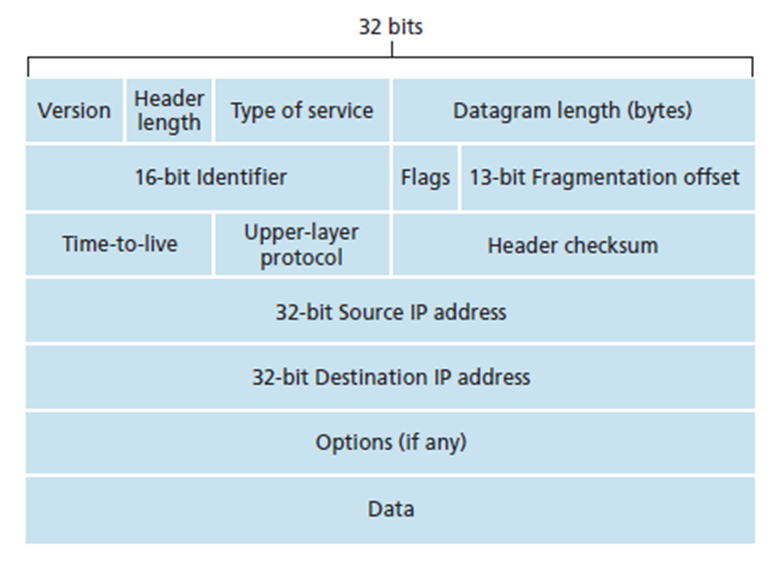
Version Number
These 4 bits specify the IP protocol version of the datagram. By
looking at the version number, the router can determine how to interpret the
remainder of the IP datagram. Different versions of IP use different datagram
formats. The datagram format for the current version of IP, IPv4 is shown in
the figure above. The datagram format for the new version of IP (IPv6) will be
discussed later.
Header Length
Because an IPv4 datagram can contain a variable number of options
(which are included in the IPv4 datagram header), these 4 bits are needed to
determine where in the IP datagram the data actually begins. Most IP datagrams
do not contain options, so the typical IP datagram has a 20-byte header.
Type of Service
The type of service (TOS) bits were included in the IPv4 header to
allow different types of IP datagrams (for example, datagrams particularly
requiring low delay, high throughput, or reliability) to be distinguished from
each other. For example, it might be useful to distinguish real-time datagrams
(such as those used by an IP telephony application) from non-real-time traffic
(for example, FTP). The specific level of service to be provided is a policy
issue determined by the router’s administrator.
Datagram Length
This is the total length of the IP datagram (header plus data),
measured in bytes. Since this filed is 16 bits long, the theoretical maximum
size of the IP datagram is 65,535 bytes. However, datagrams are rarely larger
than 1,500 bytes.
Identifier, Flags, Fragmentation Offset
These three fields have to do with so-called IP fragmentation, a
topic we will consider in depth shortly. Interestingly, the new version of IP,
IPv6, does not allow fragmentation at routers.
Time-to-live
The time-to-live (TTL) field is included to ensure that datagrams
do not circulate forever (due to, for example, a long-lived routing loop) in
the network. This field is decremented by one each time the datagram is
processed by a router. If the TTL field reaches 0, the datagram must be
dropped.
Protocol
This field is used only when an IP datagram reaches its final
destination. The value of this field indicates the specific transport-layer protocol
to which the data portion of this IP datagram should be passed. For example, a
value of 6 indicates that the data portion is passed to TCP, while a value of
17 indicates that the data is passed to UDP. For a list of all possible values,
see [IANA Protocol Numbers 2012].
Note that the protocol number in the IP datagram has a role that
is analogous to the role of the port number filed in the transport layer
segment. The protocol number is the glue that binds the network and transport
and application layers together.
Header Checksum
The header checksum aids a router in detecting bit errors in a
received IP datagram. The header checksum is computed by treating each 2 bytes
in the header as a number and summing these numbers using 1s and complement
arithmetic.
The 1s complement of this sum, known as the internet checksum, is
stored in the checksum field. A router computes the header checksum of each
received IP datagram and detects an error condition if the checksum carried in
the datagram header does not equal the computed checksum. Routers typically
discard datagrams for which an error has been detected.
Note that the checksum must be recomputed and stored again at each
router, as the TTL field, and possibly the options field as well, may change.
A question often asked at this point is, why does TCP/IP perform
error checking at both the transport and network layers? There are several
reasons for this repetition. First, note that only the IP header is checksummed
at the IP layer, while the TCP/UDP checksum is computed over the entire TCP/UDP
segment. Second, TCP/UDP and IP do not necessarily both have to belong to the
same protocol stack. TCP can , in principle, run over a different protocol (for
example ATM), and IP can carry data that will not be passed to TCP/UDP.
Source and Destination IP Addresses
When a source creates a datagram, it inserts its IP address into
the source IP address field and inserts the address of the ultimate destination
into the destination IP address field. Often the source host determines the
destination address via a DNS lookup.
Options
The options fields allow an IP header to be extended. Header
options were meant to be used rarely – hence the decision to save overhead by
not including the information in options fields in every datagram header.
However, the mere existence of options does complicate matters –
since datagram headers can be of variable length, one cannot determine a priori
where the data filed will start. Also, since some datagrams may require options
procession and others may not, the amount of time needed to process an IP
datagram at a router can vary greatly.
These considerations become particularly important for IP
processing in high-performance routers and hosts. For these reasons and others,
IP options were dropped in the IPv6 header.
Data (Payload)
Finally, we come to the last and most important field. In most
circumstances, the data field of the IP datagram contains the transport-layer
segment (TCP or UDP) to be delivered to the destination. However, the data
field can carry other types of data, such as ICMP messages.
Note that an IP datagram has a total of 20 bytes of header
(assuming no options). If the datagram carries a TCP segment, then each
(nonfragmented) datagram carries a total of 40 bytes of header (20 bytes of IP
header plus 20 bytes of TCP header) along with the application-layer message.