
Q.1 (a) What is topology? Explain star topology in brief. 03
The arrangement of a network that comprises nodes and connecting lines via sender and receiver is referred to as network topology. The various network topologies are:
- Bus Topology
- Ring Topology
- Star Topology
- Mesh Topology
- Tree Topology
- Hybrid Topology
Star topology is an arrangement of the network in which every node is connected to the central hub, switch or a central computer.
Advantages of this topology:
- If N devices are connected to each other in a star topology, then the number of cables required to connect them is N. So, it is easy to set up.
- Each device requires only 1 port i.e. to connect to the hub, therefore the total number of ports required is N.
- It is Robust. If one link fails only that link will affect and not other than that.
- Easy to fault identification and fault isolation.
- Star topology is cost-effective as it uses inexpensive coaxial cable.
Problems with this topology:
- If the concentrator (hub) on which the whole topology relies fails, the whole system will crash down.
- The cost of installation is high.
- Performance is based on the single concentrator i.e. hub.
(b) Explain various delay which are occur in data packet transmission. 04
The delays, here, means the time for which the processing of a particular packet takes place. We have the following types of delays in computer networks:
1. Transmission Delay: The time taken to transmit a packet from the host to the transmission medium is called Transmission delay.

For example, if bandwidth is 1 bps (every second 1 bit can be transmitted onto the transmission medium) and data size is 20 bits then what is the transmission delay? If in one second, 1 bit can be transmitted. To transmit 20 bits, 20 seconds would be required.
2. Propagation delay: After the packet is transmitted to the transmission medium, it has to go through the medium to reach the destination. Hence the time taken by the last bit of the packet to reach the destination is called propagation delay.

3. Queueing delay: Let the packet is received by the destination, the packet will not be processed by the destination immediately. It has to wait in a queue in something called a buffer. So the amount of time it waits in queue before being processed is called queueing delay.
4. Processing delay: Now the packet will be taken for the processing which is called processing delay.Time is taken to process the data packet by the processor that is the time required by intermediate routers to decide where to forward the packet, update TTL, perform header checksum calculations.
It depends upon the speed of the processor and the speed of the processor varies from computer to computer.
(c ) Explain functionality of Repeater, Hub, Bridge, Switch, Router and Gateway. 07
1. Repeater – A repeater operates at the physical layer. Its job is to regenerate the signal over the same network before the signal becomes too weak or corrupted to extend the length to which the signal can be transmitted over the same network. An important point to be noted about repeaters is that they do not amplify the signal. When the signal becomes weak, they copy it bit by bit and regenerate it.
2. Hub – A hub is a basically multi-port repeater. A hub connects multiple wires coming from different branches, for example, the connector in star topology which connects different stations. Hubs cannot filter data, so data packets are sent to all connected devices. In other words, the collision domain of all hosts connected through Hub remains one. Also, they do not have the intelligence to find out the best path for data packets which leads to inefficiencies and wastage.
3. Bridge – A bridge operates at the data link layer. A bridge is a repeater, with add on the functionality of filtering content by reading the MAC addresses of the source and destination. It is also used for interconnecting two LANs working on the same protocol. It has a single input and single output port, thus making it a 2 port device.

4. Switch – A switch is a multiport bridge with a buffer and a design that can boost its efficiency(a large number of ports imply less traffic) and performance. A switch is a data link layer device. The switch can perform error checking before forwarding data, which makes it very efficient as it does not forward packets that have errors and forward good packets selectively to the correct port only. In other words, the switch divides the collision domain of hosts, but the broadcast domain remains the same.
5. Routers – A router is a device like a switch that routes data packets based on their IP addresses. The router is mainly a Network Layer device. Routers normally connect LANs and WANs and have a dynamically updating routing table based on which they make decisions on routing the data packets. The router divides the broadcast domains of hosts connected through it.
6. Gateway – A gateway, as the name suggests, is a passage to connect two networks that may work upon different networking models. They work as messenger agents that take data from one system, interpret it, and transfer it to another system. Gateways are also called protocol converters and can operate at any network layer. Gateways are generally more complex than switches or routers. A gateway is also called a protocol converter.
Q.2 (a) Write short note on Domain Name System (DNS). 03
DNS is a hostname for IP address translation service. DNS is a distributed database implemented in a hierarchy of name servers. It is an application layer protocol for message exchange between clients and servers.
Requirement: Every host is identified by the IP address but remembering numbers is very difficult for the people also the IP addresses are not static therefore a mapping is required to change the domain name to the IP address. So DNS is used to convert the domain name of the websites to their numerical IP address.
DNS is a service that translates the domain name into IP addresses. This allows the users of networks to utilize user-friendly names when looking for other hosts instead of remembering the IP addresses.
For example, suppose the FTP site at EduSoft had an IP address of 132.147.165.50, most people would reach this site by specifying ftp.EduSoft.com. Therefore, the domain name is more reliable than IP address.
(b) What is HTTP? Differentiate its persistent and non-persistent types with
request-response behavior of HTTP. 04
HTTP stands for HyperText Transfer Protocol.The HTTP protocol can be used to transfer the data in the form of plain text, hypertext, audio, video, and so on.It is a protocol used to access the data on the World Wide Web (www).
- This protocol is known as HyperText Transfer Protocol because of its efficiency that allows us to use in a hypertext environment where there are rapid jumps from one document to another document.
- HTTP is similar to the FTP as it also transfers the files from one host to another host. But, HTTP is simpler than FTP as HTTP uses only one connection, i.e., no control connection to transfer the files.
- HTTP is used to carry the data in the form of MIME-like format.
- HTTP is similar to SMTP as the data is transferred between client and server. The HTTP differs from the SMTP in the way the messages are sent from the client to the server and from server to the client. SMTP messages are stored and forwarded while HTTP messages are delivered immediately.
Non-persistent: The non-persistent connection takes a total time of 2RTT + file transmission time. It takes the first RTT (round-trip time) to establish the connection between the server and the client. The second RTT is taken to request and return the object. This case stands for a single object transmission.
After the client receives the object in non-persistent, the connection is immediately closed. This is the basic difference between persistent and non-persistent. The persistent connection ensures the transfer of multiple objects over a single connection.
Persistent: A persistent connection takes 1 RTT for the connection and then transfers as many objects, as wanted, over this single connection.
RTT stands for the round-trip time taken for an object request and then its retrieval. In other words, it is the time taken to request the object from the client to the server and then retrieve it from the server back to the client.
(c ) Draw the layered architecture of OSI reference model and write at least two
services provided by each layer of the model. 07
OSI stands for Open System Interconnection is a reference model that describes how information from a software application in one computer moves through a physical medium to the software application in another computer.
- OSI consists of seven layers, and each layer performs a particular network function.
- OSI model was developed by the International Organization for Standardization (ISO) in 1984, and it is now considered as an architectural model for the inter-computer communications.
- OSI model divides the whole task into seven smaller and manageable tasks. Each layer is assigned a particular task.
- Each layer is self-contained, so that task assigned to each layer can be performed independently.

7. Application Layer: The application layer is used by end-user software such as web browsers and email clients. It provides protocols that allow software to send and receive information and present meaningful data to users. A few examples of application layer protocols are the Hypertext Transfer Protocol (HTTP), File Transfer Protocol (FTP), Post Office Protocol (POP), Simple Mail Transfer Protocol (SMTP), and Domain Name System (DNS).
6. Presentation Layer: The presentation layer prepares data for the application layer. It defines how two devices should encode, encrypt, and compress data so it is received correctly on the other end. The presentation layer takes any data transmitted by the application layer and prepares it for transmission over the session layer.
5. Session Layer: The session layer creates communication channels, called sessions, between devices. It is responsible for opening sessions, ensuring they remain open and functional while data is being transferred, and closing them when communication ends. The session layer can also set checkpoints during a data transfer—if the session is interrupted, devices can resume data transfer from the last checkpoint.
4. Transport Layer: The transport layer takes data transferred in the session layer and breaks it into “segments” on the transmitting end. It is responsible for reassembling the segments on the receiving end, turning it back into data that can be used by the session layer. The transport layer carries out flow control, sending data at a rate that matches the connection speed of the receiving device, and error control, checking if data was received incorrectly and if not, requesting it again.
3. Network Layer: The network layer has two main functions. One is breaking up segments into network packets, and reassembling the packets on the receiving end. The other is routing packets by discovering the best path across a physical network. The network layer uses network addresses (typically Internet Protocol addresses) to route packets to a destination node.
2. Data Link Layer: The data link layer establishes and terminates a connection between two physically-connected nodes on a network. It breaks up packets into frames and sends them from source to destination. This layer is composed of two parts—Logical Link Control (LLC), which identifies network protocols, performs error checking and synchronizes frames, and Media Access Control (MAC) which uses MAC addresses to connect devices and define permissions to transmit and receive data.
1. Physical Layer: The physical layer is responsible for the physical cable or wireless connection between network nodes. It defines the connector, the electrical cable or wireless technology connecting the devices, and is responsible for transmission of the raw data, which is simply a series of 0s and 1s, while taking care of bit rate control.
OR (c ) Explain DHCP and Email in detail.
Dynamic Host Configuration Protocol (DHCP) is a network management protocol used to dynamically assign an IP address to nay device, or node, on a network so they can communicate using IP (Internet Protocol). DHCP automates and centrally manages these configurations. There is no need to manually assign IP addresses to new devices. Therefore, there is no requirement for any user configuration to connect to a DHCP based network.
DHCP can be implemented on local networks as well as large enterprise networks. DHCP is the default protocol used by the most routers and networking equipment.
DHCP does the following:
- DHCP manages the provision of all the nodes or devices added or dropped from the network.
- DHCP maintains the unique IP address of the host using a DHCP server.
- It sends a request to the DHCP server whenever a client/node/device, which is configured to work with DHCP, connects to a network. The server acknowledges by providing an IP address to the client/node/device.
DHCP is also used to configure the proper subnet mask, default gateway and DNS server information on the node or device.
Electronic Mail (e-mail) is one of most widely used services of Internet. This service allows an Internet user to send a message in formatted manner (mail) to the other Internet user in any part of world. Message in mail not only contain text, but it also contains images, audio and videos data. The person who is sending mail is called sender and person who receives mail is called recipient. It is just like postal mail service.
Services provided by E-mail system :
- Composition – The composition refer to process that creates messages and answers. For composition any kind of text editor can be used.
- Transfer – Transfer means sending procedure of mail i.e. from the sender to recipient.
- Reporting – Reporting refers to confirmation for delivery of mail. It help user to check whether their mail is delivered, lost or rejected.
- Displaying – It refers to present mail in form that is understand by the user.
- Disposition – This step concern with recipient that what will recipient do after receiving mail i.e save mail, delete before reading or delete after reading.
Q.3 (a) Explain Physical Address, IP address, Port Address in brief. 03
Physical Address: In computing, a physical address (also real address, or binary address), is a memory address that is represented in the form of a binary number on the address bus circuitry in order to enable the data bus to access a particular storage cell of main memory, or a register of memory-mapped I/O device. Hence, physical address refers to either a memory location, identified in the form of a binary number, or a media access control (MAC) address.
IP Address: An IP address is a unique address that identifies a device on the internet or a local network. IP stands for "Internet Protocol," which is the set of rules governing the format of data sent via the internet or local network. An IP address has two parts: the network ID, comprising the first three numbers of the address, and a host ID, the fourth number in the address. So on your home network — 192.168. 1.1, for example – 192.168. 1 is the network ID, and the final number is the host ID.
Port Address: Port numbers identify a particular application or service on a system. An IP address identifies a machine in an IP network and determines the destination of a data packet, while port numbers identify particular applications or services on a system.
(b) Compare IPv4 and IPv6. 04
Basis for differences | IPv4 | IPv6 |
|---|---|---|
Size of IP address | IPv4 is a 32-Bit IP Address. | IPv6 is 128 Bit IP Address. |
Addressing method | IPv4 is a numeric address, and its binary bits are separated by a dot (.) | IPv6 is an alphanumeric address whose binary bits are separated by a colon (:). It also contains hexadecimal. |
Number of header fields | 12 | 8 |
Length of header filed | 20 | 40 |
Checksum | Has checksum fields | Does not have checksum fields |
Example | 12.244.233.165 | 2001:0db8:0000:0000:0000:ff00:0042:7879 |
Type of Addresses | Unicast, broadcast, and multicast. | Unicast, multicast, and anycast. |
Number of classes | IPv4 offers five different classes of IP Address. Class A to E. | lPv6 allows storing an unlimited number of IP Address. |
Configuration | You have to configure a newly installed system before it can communicate with other systems. | In IPv6, the configuration is optional, depending upon on functions needed. |
VLSM support | IPv4 support VLSM (Variable Length Subnet mask). | IPv6 does not offer support for VLSM. |
Fragmentation | Fragmentation is done by sending and forwarding routes. | Fragmentation is done by the sender. |
Routing Information Protocol (RIP) | RIP is a routing protocol supported by the routed daemon. | RIP does not support IPv6. It uses static routes. |
Network Configuration | Networks need to be configured either manually or with DHCP. IPv4 had several overlays to handle Internet growth, which require more maintenance efforts. | IPv6 support autoconfiguration capabilities. |
Best feature | Widespread use of NAT (Network address translation) devices which allows single NAT address can mask thousands of non-routable addresses, making end-to-end integrity achievable. | It allows direct addressing because of vast address Space. |
Address Mask | Use for the designated network from host portion. | Not used. |
SNMP | SNMP is a protocol used for system management. | SNMP does not support IPv6. |
Mobility & Interoperability | Relatively constrained network topologies to which move restrict mobility and interoperability capabilities. | IPv6 provides interoperability and mobility capabilities which are embedded in network devices. |
Security | Security is dependent on applications – IPv4 was not designed with security in mind. | IPSec(Internet Protocol Security) is built into the IPv6 protocol, usable with a proper key infrastructure. |
Packet size | Packet size 576 bytes required, fragmentation optional | 1208 bytes required without fragmentation |
Packet fragmentation | Allows from routers and sending host | Sending hosts only |
Packet header | Does not identify packet flow for QoS handling which includes checksum options. | Packet head contains Flow Label field that specifies packet flow for QoS handling |
DNS records | Address (A) records, maps hostnames | Address (AAAA) records, maps hostnames |
Address configuration | Manual or via DHCP | Stateless address autoconfiguration using Internet Control Message Protocol version 6 (ICMPv6) or DHCPv6 |
IP to MAC resolution | Broadcast ARP | Multicast Neighbour Solicitation |
Local subnet Group management | Internet Group Management Protocol GMP) | Multicast Listener Discovery (MLD) |
Optional Fields | Has Optional Fields | Does not have optional fields. But Extension headers are available. |
IPSec | Internet Protocol Security (IPSec) concerning network security is optional | Internet Protocol Security (IPSec) Concerning network security is mandatory |
Dynamic host configuration Server | Clients have approach DHCS (Dynamic Host Configuration server) whenever they want to connect to a network. | A Client does not have to approach any such server as they are given permanent addresses. |
Mapping | Uses ARP(Address Resolution Protocol) to map to MAC address | Uses NDP(Neighbour Discovery Protocol) to map to MAC address |
Combability with mobile devices | IPv4 address uses the dot-decimal notation. That’s why it is not suitable for mobile networks. | IPv6 address is represented in hexadecimal, colon- separated notation. IPv6 is better suited to mobile networks. |
(c ) Explain Distance Vector Routing Algorithm. 07
In distance-vector routing (DVR), each router is required to inform the topology changes to its neighboring routers periodically.
How the DVR Protocol Works
In DVR, each router maintains a routing table. It contains only one entry for each router. It contains two parts − a preferred outgoing line to use for that destination and an estimate of time (delay). Tables are updated by exchanging the information with the neighbor’s nodes.
- Each router knows the delay in reaching its neighbors (Ex − send echo request).
- Routers periodically exchange routing tables with each of their neighbors.
- It compares the delay in its local table with the delay in the neighbor’s table and the cost of reaching that neighbor.
- If the path via the neighbor has a lower cost, then the router updates its local table to forward packets to the neighbor.
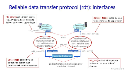
Q.3 (a) Discuss the principles of Reliable Data Transfer. 03
Principles of Reliable Data Transfer
- It’s the responsibility of a reliable data transfer protocol to implement the service abstraction of providing a reliable data transfer.
- Which can be hard because the layers bellow it might be unreliable.
- We will use the terminology “packet” rather than transport-layer “segment”.
- We will only discuss unidirectional data transfer, that is data transfer from the sending to the receiving side. Not bidirectional data transfer (full-duplex)
- With a reliable channel, notransferred data bits are corrupted (flipped from 0 to 1, or vice versa) or lost, and allare delivered in the order in which they were sent.
(b) Give difference between connection oriented and connectionless services. 04
S.NO | Connection-oriented Service | Connection-less Service |
|---|---|---|
1. | Connection-oriented service is related to the telephone system. | Connection-less service is related to the postal system. |
2. | Connection-oriented service is preferred by long and steady communication. | Connection-less Service is preferred by bursty communication. |
3. | Connection-oriented Service is necessary. | Connection-less Service is not compulsory. |
4. | Connection-oriented Service is feasible. | Connection-less Service is not feasible. |
5. | In connection-oriented Service, Congestion is not possible. | In connection-less Service, Congestion is possible. |
6. | Connection-oriented Service gives the guarantee of reliability. | Connection-less Service does not give a guarantee of reliability. |
7. | In connection-oriented Service, Packets follow the same route. | In connection-less Service, Packets do not follow the same route. |
8. | Connection-oriented services require a bandwidth of a high range. | Connection-less Service requires a bandwidth of low range. |
9. | Ex: TCP (Transmission Control Protocol) | Ex: UDP (User Datagram Protocol) |
10. | Connection-oriented requires authentication. | Connection-less Service does not require authentication. |
(c ) What do you mean by congestion and overflow? Explain the slow-start
component of the TCP congestion-control algorithm.07
- A sender attempts to communicate to a receiver. The sender’s initial packet contains a small congestion window, which is determined based on the sender’s maximum window.
- The receiver acknowledges the packet and responds with its own window size. If the receiver fails to respond, the sender knows not to continue sending data.
- After receiving the acknowledgement, the sender increases the next packet’s window size. The window size gradually increases until the receiver can no longer acknowledge each packet, or until either the sender or the receiver’s window limit is reached.
- Once a limit has been determined, slow start’s job is done. Other congestion control algorithms take over to maintain the speed of the connection.
Q.4 (a) Explain packet fragmentation with example. 03
Every packet based network has an MTU (Maximum Transmission Unit) size. The MTU is the size of the largest packet that that network can transmit.
Packets larger than the allowable MTU must be divided into smaller packets or fragments to enable them to traverse the network.
| Network | Standard MTU |
|---|---|
| Ethernet | 1500 |
| Token Ring | 4096 |
If a 2,366 byte packet enters an Ethernet network with a default MTU size, it must be fragmented into two packets.
The first packet will:
- Be 1,500 bytes in length. 20 bytes will be the IP header, 24 bytes will be the TCP header, and 1,456 bytes will be data.
- Have a DF bit equal to 0 to mean “May Fragment” and an MF bit equal to 1 to mean “More Fragments.”
- Have a Fragmentation Offset of 0.
The second packet will:
- Be 910 bytes in length. 20 bytes will be the IP header, 24 bytes will be the TCP header, and 866 bytes will be data.
- Have the DF bit equal to 0 to mean “May Fragment” and the MF bit equal to 0 to mean “Last Fragment.”
- Have a Fragmentation Offset of 182 (Note: 182 is 1456 divided by 8).
In broadcast routing, packets are sent to all nodes even if they do not want it. But in Multicast routing, the data is sent to only nodes which wants to receive the packets. The router must know that there are nodes, which wish to receive multicast packets (or stream) then only it should forward.
Broadcast routing
By default, the broadcast packets are not routed and forwarded by the routers on any network. Routers create broadcast domains. But it can be configured to forward broadcasts in some special cases. A broadcast message is destined to all network devices.
Broadcast routing can be done in two ways (algorithm):
A router creates a data packet and then sends it to each host one by one. In this case, the router creates multiple copies of single data packet with different destination addresses. All packets are sent as unicast but because they are sent to all, it simulates as if router is broadcasting.
- This method consumes lots of bandwidth and router must destination address of each node.
- Secondly, when router receives a packet that is to be broadcasted, it simply floods those packets out of all interfaces. All routers are configured in the same way.
This method is easy on router's CPU but may cause the problem of duplicate packets received from peer routers.
Reverse path forwarding is a technique, in which router knows in advance about its predecessor from where it should receive broadcast. This technique is used to detect and discard duplicates.
Multicast Routing
Multicast routing is special case of broadcast routing with significance difference and challenges. In broadcast routing, packets are sent to all nodes even if they do not want it. But in Multicast routing, the data is sent to only nodes which wants to receive the packets.
The router must know that there are nodes, which wish to receive multicast packets (or stream) then only it should forward. Multicast routing works spanning tree protocol to avoid looping.
Multicast routing also uses reverse path Forwarding technique, to detect and discard duplicates and loops.

193.1.2.0 to 193.1.2.127 - Subnet id of Subnet-1 is : 193.1.2.0
- Direct Broadcast id of Subnet-1 is : 193.1.2.127
- Total number of host possible is : 126 (Out of 128, 2 id’s are used for Subnet id & Direct Broadcast id)
- Subnet mask of Subnet- 1 is : 255.255.255.128
For Subnet-2: The first bit chosen from the host id part is one and the range will be from (193.1.2.100000000 till you get all 1’s in the host ID part i.e, 193.1.2.11111111). Thus, the range of subnet-2:
193.1.2.128 to 193.1.2.255 - Subnet id of Subnet-2 is : 193.1.2.128
- Direct Broadcast id of Subnet-2 is : 193.1.2.255
- Total number of host possible is : 126 (Out of 128, 2 id’s are used for Subnet id & Direct Broadcast id)
- Subnet mask of Subnet- 2 is : 255.255.255.192
Finally, after using the subnetting the total number of usable hosts are reduced from 254 to 252.
Q.4 (a) Give differences between TCP and UDP. 03
| Basis | Transmission control protocol (TCP) | User datagram protocol (UDP) |
|---|---|---|
| Type of Service | TCP is a connection-oriented protocol. Connection-orientation means that the communicating devices should establish a connection before transmitting data and should close the connection after transmitting the data. | UDP is the Datagram-oriented protocol. This is because there is no overhead for opening a connection, maintaining a connection, and terminating a connection. UDP is efficient for broadcast and multicast types of network transmission. |
| Reliability | TCP is reliable as it guarantees the delivery of data to the destination router. | The delivery of data to the destination cannot be guaranteed in UDP. |
| Error checking mechanism | TCP provides extensive error-checking mechanisms. It is because it provides flow control and acknowledgment of data. | UDP has only the basic error checking mechanism using checksums. |
| Acknowledgment | An acknowledgment segment is present. | No acknowledgment segment. |
| Sequence | Sequencing of data is a feature of Transmission Control Protocol (TCP). this means that packets arrive in order at the receiver. | There is no sequencing of data in UDP. If the order is required, it has to be managed by the application layer. |
| Speed | TCP is comparatively slower than UDP. | UDP is faster, simpler, and more efficient than TCP. |
| Retransmission | Retransmission of lost packets is possible in TCP, but not in UDP. | There is no retransmission of lost packets in the User Datagram Protocol (UDP). |
| Header Length | TCP has a (20-60) bytes variable length header. | UDP has an 8 bytes fixed-length header. |
| Weight | TCP is heavy-weight. | UDP is lightweight. |
| Handshaking Techniques | Uses handshakes such as SYN, ACK, SYN-ACK | It’s a connectionless protocol i.e. No handshake |
| Broadcasting | TCP doesn’t support Broadcasting. | UDP supports Broadcasting. |
| Protocols | TCP is used by HTTP, HTTPs, FTP, SMTP and Telnet. | UDP is used by DNS, DHCP, TFTP, SNMP, RIP, and VoIP. |
| Stream Type | The TCP connection is a byte stream. | UDP connection is message stream. |
| Overhead | Low but higher than UDP. | Very low. |
(b) What is socket? Explain its importance at transport layer protocols. 04
A socket is one endpoint of a two-way communication link between two programs running on the network. The application creates a socket. Socket is an interface between application layer and transport layer.It is an interface (a “door”) into which an application process can both send and receive message to/from another application process (remote/local application process). Socket is also referred as the application programmer’s interface (API) between the application and the network.
Need of SocketWhen we desire a communication between two applications possibly running on different machines, we need sockets. Requirement of socket is to build any Network Application i.e., Web browsers, FTP etc…
How Socket Works?

There are two different programs running on two different machines in network. Client program wants to communicate with server program. Client select any free port from client machine and send data to server process. Server select port which is bind with particular server process. That port is called agreed or specific port. After that logical connection is created between client and server. Server received client process at agreed/specific port. Then communication is started between server and client.
(c ) Discuss transport layer multiplexing and demultiplexing concepts. 07
Multiplexing
Multiplexing is the process of collecting the data from multiple application processes of the sender, enveloping that data with headers and sending them as a whole to the intended receiver.
- In Multiplexing at the Transport Layer, the data is collected from various application processes. These segments contain the source port number, destination port number, header files, and data.
- These segments are passed to the Network Layer which adds the source and destination IP address to get the datagram.
Demultiplexing
Delivering the received segments at the receiver side to the correct app layer processes is called demultiplexing.
- The destination host receives the IP datagrams; each datagram has a source IP address and a destination IP address.
- Each datagram carries 1 transport layer segment.
- Each segment has the source and destination port number.
- The destination host uses the IP addresses and port numbers to direct the segment to the appropriate socket.
![]()
.jpg)
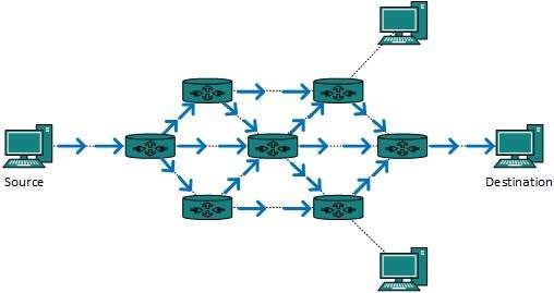
Multiplexing and demultiplexing are just concepts that describe the process of the transmission of data generated by different applications simultaneously. When the data arrives at the Transport layer, each data segment is independently processed and sent to its appropriate application in the destination machine.
![]()
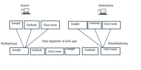
The main objective of multiplexing and demultiplexing is to allow us to use a multitude of applications simultaneously.
- The above figure shows that the source computer is using Google, Outlook, and Chat applications at the same time.
- All the data is forwarded to a destination computer.
- Each application has a segment put on a wire to be transmitted. It signifies that all applications are running simultaneously.
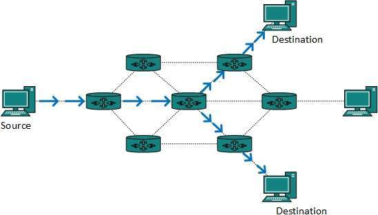
- Without multiplexing/demultiplexing exists, a user can use only one application at a time because only the segments of that application are put on the wire and transmitted. For clarification, see the figure below −
![]()
.jpg)
In the above figure, the Application layer has generated data, and then passed it down to the Transport layer to be segmented.
- After segmenting the data, port numbers are given to each segment to be ready for transmission.
- Then the segments are put on a wire to travel across the network to the destination. This process is called "multiplexing".
- When the transmitted segments reach the Transport layer of the destination, they are automatically sent up to their appropriate applications. This process is called "demultiplexing".
Q.5 (a) Discuss CSMA/CD Protocol. 03
Carrier Sense Multiple Access with Collision Detection (CSMA/CD) is a network protocol for carrier transmission that operates in the Medium Access Control (MAC) layer. It senses or listens whether the shared channel for transmission is busy or not, and defers transmissions until the channel is free. The collision detection technology detects collisions by sensing transmissions from other stations. On detection of a collision, the station stops transmitting, sends a jam signal, and then waits for a random time interval before retransmission.
Algorithms
The algorithm of CSMA/CD is:
- When a frame is ready, the transmitting station checks whether the channel is idle or busy.
- If the channel is busy, the station waits until the channel becomes idle.
- If the channel is idle, the station starts transmitting and continually monitors the channel to detect collision.
- If a collision is detected, the station starts the collision resolution algorithm.
- The station resets the retransmission counters and completes frame transmission.
The algorithm of Collision Resolution is:
- The station continues transmission of the current frame for a specified time along with a jam signal, to ensure that all the other stations detect collision.
- The station increments the retransmission counter.
- If the maximum number of retransmission attempts is reached, then the station aborts transmission.
- Otherwise, the station waits for a backoff period which is generally a function of the number of collisions and restart main algorithm.
The following flowchart summarizes the algorithms:

- Though this algorithm detects collisions, it does not reduce the number of collisions.
- It is not appropriate for large networks performance degrades exponentially when more stations are added.
(b) Explain CRC code generation with example. 04
- Though this algorithm detects collisions, it does not reduce the number of collisions.
- It is not appropriate for large networks performance degrades exponentially when more stations are added.
Cyclic Redundancy Check (CRC) is another error detection technique to detect errors in data that has been transmitted on a communications link. A sending device applies a 16 or 32 bit polynomial to a block of data that is to be transmitted and appends the resulting cyclic redundancy check (CRC) to the block. The receiving end applies the same polynomial to the data and compares its result with the result appended by the sender. If they agree, the data has been received successfully. If not, the sender can be notified to resend the block of data.
Cyclic Redundancy Check (CRC) is another error detection technique to detect errors in data that has been transmitted on a communications link. A sending device applies a 16 or 32 bit polynomial to a block of data that is to be transmitted and appends the resulting cyclic redundancy check (CRC) to the block. The receiving end applies the same polynomial to the data and compares its result with the result appended by the sender. If they agree, the data has been received successfully. If not, the sender can be notified to resend the block of data.
Example
Assume that –
(a) data is 10110.
(b) code generator is 1101. (Code generator can also be mentioned in polynomial : $ x^3+x^2+1 $)
Note – Code generator is always mentioned in the question.
(a) data is 10110.
(b) code generator is 1101. (Code generator can also be mentioned in polynomial : $ x^3+x^2+1 $)
Calculate CRC Bits:
Now, we will see how to calculate CRC bits using above data.
While calculating the CRC bits, we pad (n-1) 0’s to the message bits, where ‘n’ = no of bits in the code generator.
In the above code, code generator is 1101. So, there is total 4 bits. So, we will append 000 with the data.
Finally, Cyclic Redundancy check will be generated as shown below –

CRC calculation by sender
Cyclic redundancy check is 101. Thus, the sender sends 10110101 to the receiver.
While calculating the CRC bits, we pad (n-1) 0’s to the message bits, where ‘n’ = no of bits in the code generator.
CRC calculation by sender
At Receiver Side
- Receiver has same generator G(x).
- Receiver divides received data (data + CRC) with generator.
- If remainder is zero, data is correctly received.
- Else, there is error.
Assume the received message is 10110110.
Calculate CRC Bits:
It does not add any padding bits, rather calculates from the entire received code word.

CRC calculation by receiver
The CRC bits are calculated to be different. Thus, there is an error detected.
(c ) Describe Go Back N and Selective Repeat protocol. 07
It does not add any padding bits, rather calculates from the entire received code word.
CRC calculation by receiver
The CRC bits are calculated to be different. Thus, there is an error detected.
What is Go-Back-N Protocol?
The Go-Back-N ARQ protocol is a variant of the Automatic Repeat Request (ARQ) protocol.
- The sender sends several frames determined by a window size even if the receiver does not respond with an acknowledgment (ACK) packet.
- A transmit window size of N, and a receive window size of 1 is a particular case of the basic sliding window protocol. It can send N frames to the peer before requesting an acknowledgment.
- It works on the notion of protocol pipelining, which allows numerous frames to be delivered before the first frame is acknowledged.
- The shelves in Go-Back-N ARQ are numbered consecutively because Go-Back-N ARQ provides multiple brackets at once, necessitating a numbering strategy to identify one frame from another. These numbers are referred to as sequential numbers.
- The maximum number of frames that can be sent at once is entirely dependent on the sender's window size. All structures in the current window will be retransmitted if a frame's acknowledgment is not received within the agreed-upon time frame.
What is Selective Repeat Protocol?
Selective Repeat is a variant of the Automated Repeat Request (ARQ) protocol used in reliable communications to handle sequence numbers and retransmissions.
- Particular repetition allows the transmitter to deliver a set number of frames without waiting for individual ACK from the recipient, as in Go-Back-N ARQ.
- It employs two equal-sized windows: a sending window for storing frames to be sent and a receiving window for storing frames received by the receiver. The size is half of the frame's maximum sequence number. For example, if the sequence number is from 0–15, the window size will be 8.
- Even if it does not receive acknowledgment for any frame in the interim, the Selective Repeat protocol allows it to send several frames based on the availability of structures in the sending window.
- The size of the transmitting window determines the maximum number of frames that can be sent.
Difference between Go-Back-N and Selective Repeat Protocol
The following table highlights the major differences between the Go-Back-N and the Selective Repeat protocols −
| Key | Go-Back-N | Selective Repeat |
|---|---|---|
| Definition | In Go-Back-N, if a sent frame is found suspected or damaged, then all the frames are retransmitted till the last packet. | In Selective Repeat, only the suspected or damaged frames are retransmitted. |
| Sender Window Size | Sender Window is of size N. | Sender Window size is same as N. |
| Receiver Window Size | Receiver Window Size is 1. | Receiver Window Size is N. |
| Complexity | Go-Back-N is easier to implement. | In Selective Repeat, receiver window needs to sort the frames. |
| Efficiency | Efficiency of Go-Back-N = N / (1 + 2a), where "a" is ratio of propagation delay vs. transmission delay and "N" is the number of packets sent. | Efficiency of Selective Repeat = N / (1 + 2a). |
| Acknowledgement | Acknowledgement type is cumulative. | Acknowledgement type is individual. |
| Sorting | Neither the sender nor the recipient requires sorting. | To sort the frames on the receiver side, sorting is needed. |
| Out-of-order Packets | Out-of-Order packets are rejected, and the entire window is re-transmitted. | Out-of-Order packets are accepted in the selective Repeat protocol. |
| Minimum Sequence Number | The Minimum Sequence Number in the Go-Back-N protocol is N+1, where "N" is the number of packets sent. | The Minimum Sequence Number in the Selective Repeat protocol is 2N, where "N" is the number of packets transmitted. |
Q.5 (a) Discuss parity check for error detection in data transfer. 03
Parity Checking of Error Detection
It is the simplest technique for detecting and correcting errors. The MSB of an 8-bits word is used as the parity bit and the remaining 7 bits are used as data or message bits. The parity of 8-bits transmitted word can be either even parity or odd parity.
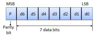
Even parity -- Even parity means the number of 1's in the given word including the parity bit should be even (2,4,6,....).
Odd parity -- Odd parity means the number of 1's in the given word including the parity bit should be odd (1,3,5,....).
Use of Parity Bit
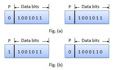
The parity bit can be set to 0 and 1 depending on the type of the parity required.
For even parity, this bit is set to 1 or 0 such that the no. of "1 bits" in the entire word is even. Shown in fig. (a).
For odd parity, this bit is set to 1 or 0 such that the no. of "1 bits" in the entire word is odd. Shown in fig. (b).
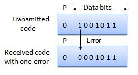
How Does Error Detection Take Place?
Parity checking at the receiver can detect the presence of an error if the parity of the receiver signal is different from the expected parity. That means, if it is known that the parity of the transmitted signal is always going to be "even" and if the received signal has an odd parity, then the receiver can conclude that the received signal is not correct. If an error is detected, then the receiver will ignore the received byte and request for retransmission of the same byte to the transmitter.
(b) What do you mean by random access protocols? Explain slotted ALOHA in brief.04
In this protocol, all the station has the equal priority to send the data over a channel. In random access protocol, one or more stations cannot depend on another station nor any station control another station. Depending on the channel's state (idle or busy), each station transmits the data frame. However, if more than one station sends the data over a channel, there may be a collision or data conflict. Due to the collision, the data frame packets may be lost or changed. And hence, it does not receive by the receiver end.
Following are the different methods of random-access protocols for broadcasting frames on the channel.
- Aloha
- CSMA
- CSMA/CD
- CSMA/CA
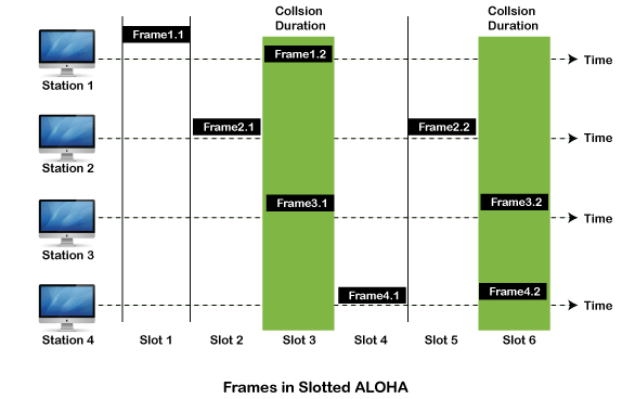
Slotted Aloha
The slotted Aloha is designed to overcome the pure Aloha's efficiency because pure Aloha has a very high possibility of frame hitting. In slotted Aloha, the shared channel is divided into a fixed time interval called slots. So that, if a station wants to send a frame to a shared channel, the frame can only be sent at the beginning of the slot, and only one frame is allowed to be sent to each slot. And if the stations are unable to send data to the beginning of the slot, the station will have to wait until the beginning of the slot for the next time. However, the possibility of a collision remains when trying to send a frame at the beginning of two or more station time slot.
- Maximum throughput occurs in the slotted Aloha when G = 1 that is 37%.
- The probability of successfully transmitting the data frame in the slotted Aloha is S = G * e ^ - 2 G.
- The total vulnerable time required in slotted Aloha is Tfr.

The preamble field
The preamble field is 7 bytes long. It contains a string of 7 bytes. Each byte alternatively stores 1 and 0 to make the pattern '10101010'. Preamble bytes help the receiving device to identify the beginning of an Ethernet frame. When a device receives 7 continuous bytes of the same pattern (10101010), it assumes that the incoming data is an Ethernet frame and it locks the incoming bit-stream.
The SFD field
The SFD (Start Frame Delimiter) field is 1 byte long. It contains a string of 1 byte. This byte also stores the same pattern, except the last bit. In the last bit, it stores 1 instead of the 0. The following image shows both fields with their related bytes respectively.

The SFD byte indicates the receiving device that the next byte is the destination MAC address of the Ethernet frame.
Destination MAC address
This field is 6 bytes long. It contains the MAC address of the destination device. MAC address is 6 bytes or 48 bits (1 byte = 8 bits, 6x8 = 48bits) long. For convenience, usually, it is written as 12-digit hexadecimal numbers (such as 0000.0A12.1234).
The destination MAC address allows the receiving device to determine whether an incoming frame is intended for it or not. If a frame is not intended for the receiving device, the receiving device discards that frame.
Source MAC address
This field is also 6 bytes long. It contains the MAC address of the source device. It helps the receiving device in identifying the source device. The following image shows an example of both types of address in the frame.

Type field
This field is 2 bytes long. This field stores information about the protocol of the upper layer (network layer).
The Data Link layer of the source computer prepares, packs and loads the Ethernet frame in the media. The Data link layer of the destination computer picks the Ethernet frame from the media. After picking the Ethernet frame, the Data link layer of the destination computer unpacks, processes, and hands over that Ethernet frame to the upper layer for further processing.
If multiple protocols are running in the upper (network) layer of the destination computer, the data link layer will fail to hand over the received frame to the upper layer as it does not know to which protocol it should give the received frame.
The type field solves this issue. This field allows the sender computer to insert the information of the upper layer protocol. Through this information, the data link layer of the destination computer can easily determine the upper layer protocol to which it should hand over the received frame.
Modern LAN implementations mostly use the IP protocol in the network layer. There are two variants of the IP protocol; IPv4 and IPv6. If the type field has value IP or ox800, the frame is carrying the data of the IPv4 protocol. If the type field has value IPv6 or 0x86dd, the frame is carrying the data of the IPv6 protocol.
The following image shows an example of the type field for both IP variants.

Data and Pad field
This field stores the encapsulated data of the upper layer. This field has a size limit of 46 bytes (minimum) to 1500 bytes (maximum). Due to this limit, the network (upper) layer can't pack more or less data in a single packet (encapsulated data of the upper layer). If data is less than the minimum requirement, padding is added. If data is more than the maximum limit, extra data is packed in the next packet.
FCS (Frame Check Sequence)
This field is 4 bytes long. This field stores a 4 bytes value that is used to check whether the received frame is intact or not. The sender device takes all fields of the frame except the FCS field, and runs them through an algorithm, known as the CRC (Cyclic Redundancy Check). The CRC algorithm generates a 4-byte result, which is placed in this FCS field.
When the destination device receives a frame, it takes the same fields and runs them through the same algorithm. If the result matches with the value stored in the FCS field, the frame is considered good and is processed further. If both values do not match, the frame is considered bad and is dropped.